設備:Arduino UNO、C4Lab Case Kit Zebra、Kuman 3.5 吋 TFT LCD 以及一張 micro-SD 卡。
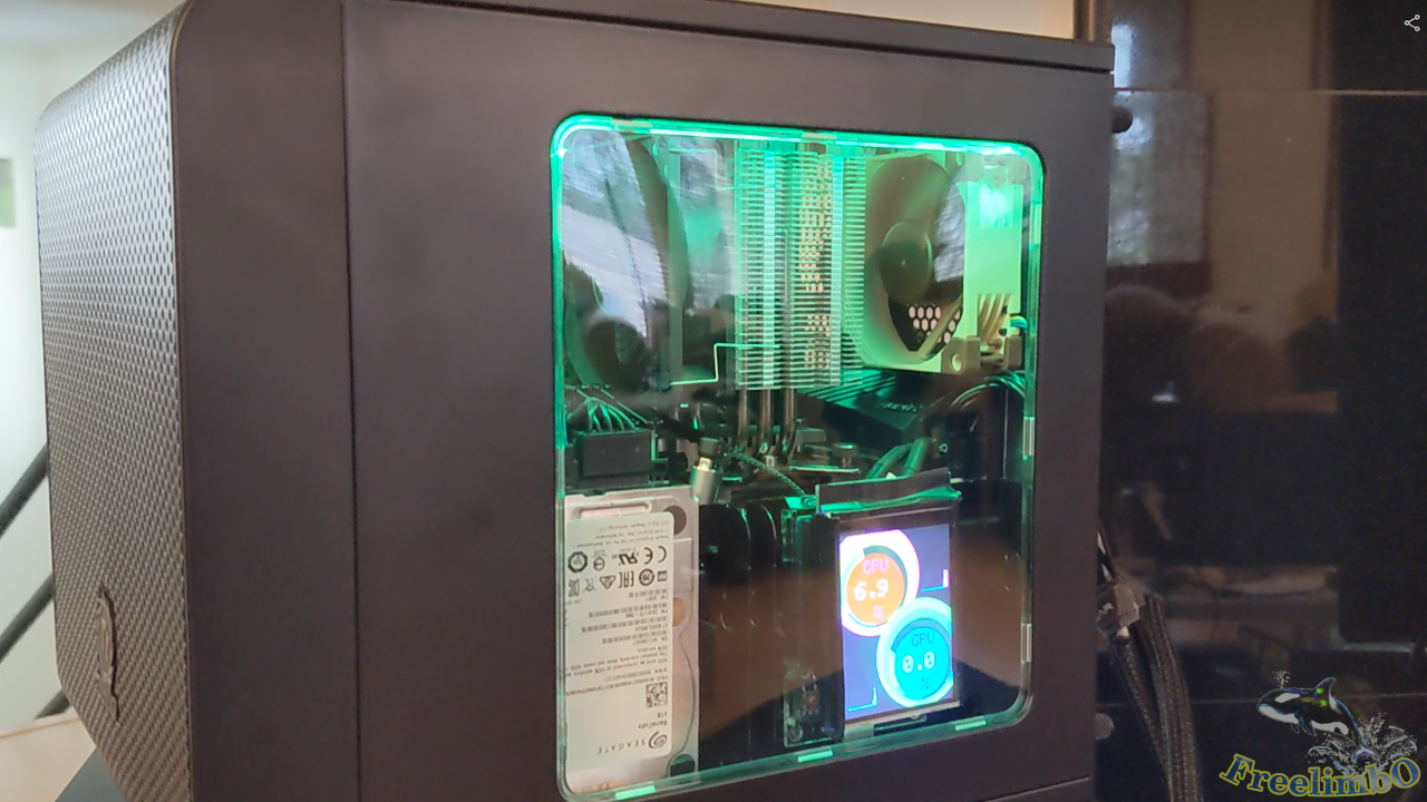
自從組裝了我的遊戲電腦後,我在玩遊戲或進行遊戲直播時,經常想查看 CPU 和 GPU 的負載狀況。我知道有些 Windows 應用程式會在螢幕上建立疊加層來顯示硬體狀態,但我希望螢幕能保持盡可能簡潔。 因此我想到一個解決方案:打造一塊額外的微型螢幕,作為電腦面板使用。
微控制器:Arduino UNO R3 開發板
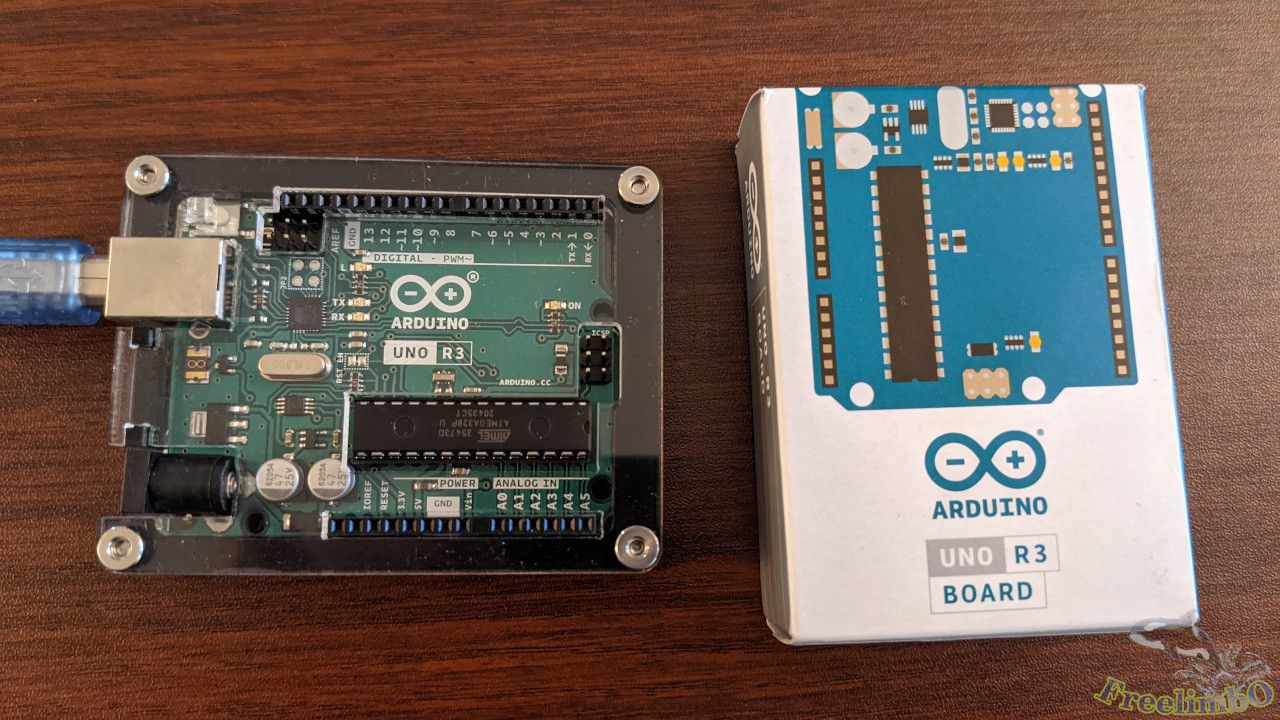
Arduino UNO R3 的功耗極低。它既可透過電源插孔輸入 9V 50mA 供電,也可透過 USB-A 插孔輸入 5V 40mA 供電。這點非常理想,因為無論我的遊戲電腦是否開機,我都會使用這台裝置。 我希望這塊面板能夠全天候運作,每週 7 天不間斷。
我為 Arduino 找到了一個充滿藝術感的機殼。它看似由壓克力板切割而成,組裝過程也別具創意,因為機殼是以透明板片的形式提供。我將這些板片層層堆疊,組成了機殼。組裝完成後,所有 I/O 埠都能無障礙地外露。真的非常酷且美觀。
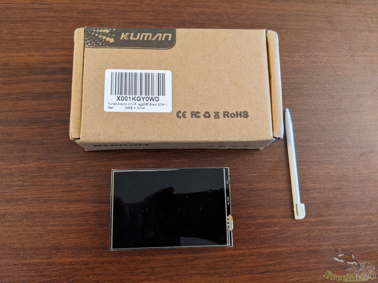
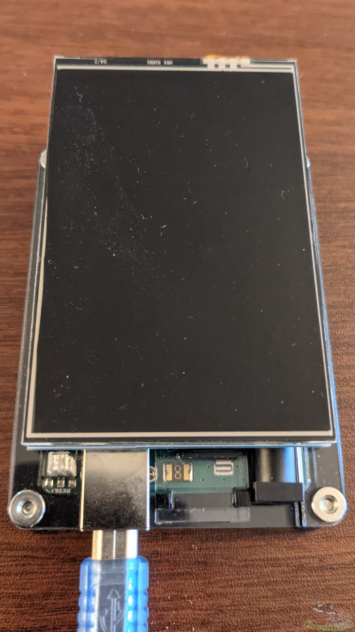
顯示器:Kuman 3.5 吋 TFT LCD
|
|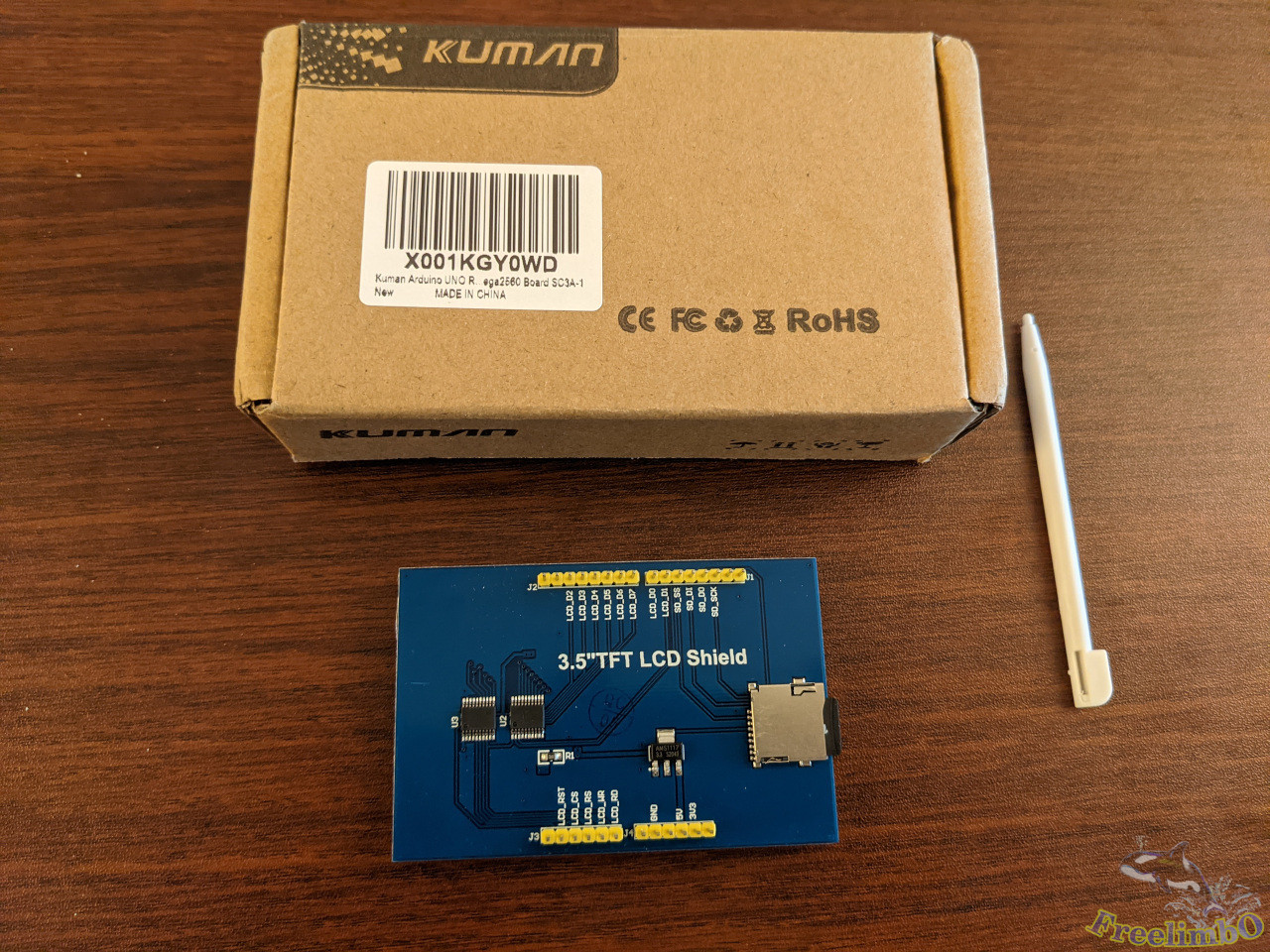
這塊 3.5 吋 LCD 顯示器的解析度為 320x480 像素,足以顯示我所需的所有硬體資訊。由於它實際上是電阻式觸控面板,因此隨附了一支觸控筆,但我並不需要觸控螢幕功能。 我打算將這塊 PC 面板安裝在 Thermaltake Core V1 的透明視窗內,並讓它顯示一些預先編程的數字和圖表。
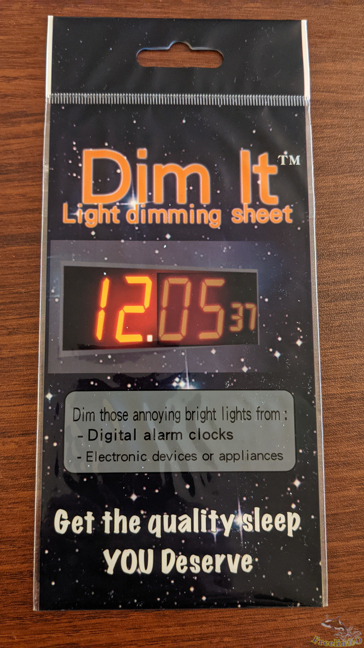
我唯一的抱怨是這塊小巧的 LCD 沒有調暗亮度的功能。如果我經常盯著螢幕看,眼睛會感到疲勞。有些人試著修改 LCD 背面的電路,但我只想試著用濾光片來解決這個問題。
組裝完成的裝置
|
|
|
|
| Dim-It 濾光片 |
Arduino 與 LCD 的整合 |
這片濾光片安裝在顯示器上非常簡單,而且效果極佳。亮度被調暗到非常舒適的程度。
將 LCD 顯示器疊放在 Arduino 板上同樣輕鬆。看起來就像是市售產品,對吧?
設計圖形介面
電腦開機時的運作行為
雖然可用來呈現六項讀數的區域相當有限,但我仍希望圖形面板能稍具設計感。因此,針對我最感興趣的六項數值,我設計出以下方案:
- CPU 負載:多核心的平均負載百分比。數字。
- CPU 溫度:封裝溫度。一個彎曲的溫度計。
- 記憶體負載:記錄過往記憶體使用歷史。直方圖。
- GPU 負載:GPU 核心負載或視訊引擎負載。數值
- GPU 溫度:GPU 核心溫度。彎曲的溫度計。
- GDDR 負載:GPU 記憶體。直方圖。
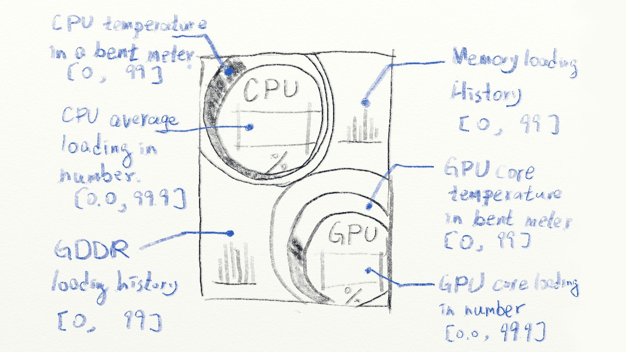
如上所示,將採用三種呈現風格。數值顯示處理器負載,彎曲的溫度計顯示溫度,直方圖則顯示記憶體負載。 上方區域用於顯示 CPU 相關資訊,下方則用於顯示 GPU 相關讀數。
若情況允許,我希望溫度計能像真實儀表一樣運作。刻度必須漸進地上升或下降,且顏色必須採用漸變彩虹風格。當溫度升至接近 100 攝氏度時,刻度的末端應接近紅色,以呈現核心的熱度。
至於直方圖中的歷史資料,我設計成從最舊的記憶體負載開始,滾動顯示至最新資料。滾動方向由右向左,因此最新的負載數據會顯示在右側。
關機時的運作行為
任何遊戲電腦都必然耗電量極大,這意味著在不玩遊戲時,我會關閉電腦。因此,我想將電腦主機面板用作數位相框。我發現隨附 LCD 的函式庫和範例中,正好包含了一種完全符合我需求的數位相框實作方案。所以這部分相當簡單。
以下是為數位相框模式準備照片的步驟:
- 我需要一張 micro-SD 卡。
- 準備一些裁切為 320x480 垂直尺寸的 BMP 格式照片。
- 將這些照片依序編號,以便 Arduino 程式能輕鬆地在照片間循環瀏覽。
- 將所有 BMP 照片直接放入 micro-SD 卡中,無需建立任何資料夾目錄。
實作
由於我要從電腦擷取硬體資訊並顯示在微型螢幕上,因此實作包含兩個部分:電腦端與 Arduino 端。
Windows 電腦端的 Python 程式碼
我發現主機電腦最好採用 Windows 系統,這樣 OpenHardwareMonitor 才能正確擷取硬體資訊。請前往 [Open Hardware Monitor 的下載頁面](https://openhardwaremonitor.org/downloads/
) 取得該工具。安裝時可能需要預先安裝某些先決條件,例如 Microsoft .NET Framework。
Python 程式碼可分為三個部分:
- 與 Arduino 進行串列埠通訊。
- 在 OpenHardwareMonitor 中搜尋感測器索引。
- 偵測讀數並處理資料。
串列埠
 1
 2
 3
 4
 5
 6
 7
 8
 9
10
11
12
13
14
15
16
17
18
19
20
21
22
23
24
25
26
27
28
29
30
31
32
33
34
35
36
37
38
39
40
41
42
43
44
45
46
47
48
49
50
51
52
53
54
55
56
57
58
59
|
# -*- coding: utf-8 -*-
import serial
import time
from datetime import datetime
from datetime import timedelta
import wmi # Windows Management INstrumentation
import math

startMarker = '<'
endMarker = '>'
dataStarted = False
dataBuf = ""
messageComplete = False
isInitial = True

def setupSerial(baudRate, serialPortName):
    global  serialPort
    serialPort = serial.Serial(port= serialPortName, baudrate = baudRate, timeout=0, rtscts=True)
    print("Serial port " + serialPortName + " opened  Baudrate " + str(baudRate))
    waitForArduino()

def sendToArduino(stringToSend):
    global startMarker, endMarker, serialPort
    stringWithMarkers = (startMarker)
    stringWithMarkers += stringToSend
    stringWithMarkers += (endMarker)
    serialPort.write(stringWithMarkers.encode('utf-8')) # encode needed for Python3

def recvLikeArduino():
    global startMarker, endMarker, serialPort, dataStarted, dataBuf, messageComplete

    if serialPort.inWaiting() > 0 and messageComplete == False:
        x = serialPort.read().decode("utf-8") # decode needed for Python3

        if dataStarted == True:
            if x != endMarker:
                dataBuf = dataBuf + x
            else:
                dataStarted = False
                messageComplete = True
        elif x == startMarker:
            dataBuf = ''
            dataStarted = True
    if (messageComplete == True):
        messageComplete = False
        return dataBuf
    else:
        return "XXX"

def waitForArduino():
    print("Waiting for Arduino to reset")
    msg = ""
    while msg.find("Arduino is ready") == -1:
        msg = recvLikeArduino()
        if not (msg == 'XXX'):
            print(msg)

setupSerial(115200, "COM3") # For Windows
#setupSerial(115200, "/dev/ttyACM0") # For Ubuntu
|
Arduino 透過 USB 串列埠與主機電腦進行訊息傳輸。這四個函式是借用自 [Arduino 官方論壇](https://forum.arduino.cc/t/pc-arduino-comms-using-python-updated/574496
)。由於其運作已十分順暢,因此我並未進行修改。感謝 [Robin2](https://forum.arduino.cc/u/robin2/summary
)。這些函式負責處理設定、傳送、接收,以及過濾不需要的訊息。
搜尋感測器索引
 1
 2
 3
 4
 5
 6
 7
 8
 9
10
11
12
13
14
15
16
17
18
19
20
21
22
23
24
25
26
27
|
cpu_temp_index = 0;
cpu_load_indices = [0, 0, 0, 0, 0, 0, 0, 0]
gpu_temp_index = 0;
gpu_load_index = 0;
mem_index = 0;
gddr_index = 0;
w = wmi.WMI(namespace="root\\OpenHardwareMonitor")
sensors = w.Sensor()

def searchIndices():
    global w, sensors, cpu_temp_index, cpu_load_indices, gpu_temp_index, gpu_load_index, mem_index, gddr_index

    print("Checking index...")
    time.sleep(1)
    sensors = w.Sensor()

    dummyIdx = 0;

    for i, sensor in enumerate(sensors):
        if sensor.SensorType==u'Temperature' and 'CPU Package' == sensor.Name:
            cpu_temp_index = i
            print(i, sensor.Name, sensor.SensorType, sensor.Value)
        ...
        elif sensor.SensorType==u'Load' and 'GPU Memory' == sensor.Name:
        #elif sensor.SensorType==u'Clock' and 'GPU Memory' == sensor.Name:
            gddr_index = i
            print(i, sensor.Name, sensor.SensorType, sensor.Value/1500)
|
我使用 Windows 管理儀表 (WMI) 與 OpenHardwareMonitor 進行通訊。感測器類別的屬性可透過 OpenHardwareMonitor 的圖形化使用者介面 (GUI) 查詢。
為了提高系統的穩健性並縮短索引搜尋時間,我將偵測邏輯封裝成函式,並僅記錄感測器清單中六個索引的值。此時並未進行實際的偵測作業。
讀取偵測與資料處理
 1
 2
 3
 4
 5
 6
 7
 8
 9
10
11
12
13
14
15
16
17
18
19
20
21
22
23
24
25
26
27
28
29
30
31
32
33
34
35
36
37
38
39
40
41
42
43
44
45
46
47
48
49
50
51
|
prevDateTime = datetime.now()
deltaThreshold = timedelta( seconds = 20)
diff = timedelta( seconds = 0)
deg = 0;
while True:
    arduinoReq = recvLikeArduino()
    if not (arduinoReq == u'XXX'):
        sensors = w.Sensor()
        currDateTime = datetime.now()
        diff = currDateTime - prevDateTime
        #print("now =", currDateTime, ", diff = ", diff)

        #print("isInitial: ", isInitial)
        #print("diff: ", diff)
        if isInitial or diff > deltaThreshold:
            searchIndices()
            isInitial = False

        prevDateTime = datetime.now()
        #print("now =", prevDateTime)

        try:
            cpu_temp = min(99.9, sensors[cpu_temp_index].Value)
            if cpu_temp == 0:
                isInitial = True
                continue
        except IndexError:
            print("cpu_temp_index out of range.")
            isInitial = True
            continue
        ...
        try:
            gddr = min(99.9, sensors[gddr_index].Value/1500*100)
        except IndexError:
            print("gddr_index out of range.")
            isInitial = True
            continue
				''' # Fake sinusoidal signal"
        rad = 6*deg / 180.0 * 3.1415926;
        mem = 20 + 20* math.sin(rad)
        deg += 1
				'''
        newString = "{:.1f}".format(cpu_temp)
        returnMsg = newString
        #print(cpu_temp_index, "CPU Temp: " + newString)
        ...
        newString = ",{:.1f}".format(gddr)
        returnMsg += newString
        #print("GPU Memory: " + newString)

        sendToArduino(returnMsg)
|
我發現這些索引在從睡眠或休眠狀態喚醒後可能會改變。必須有某種例外處理程序來觸發感測器索引偵測函式。接著,我將字串格式化,並透過序列埠傳送至 Arduino。
若讀者尚未設定 OpenHardwareMonitor,我為早期開發階段加入了一個偽正弦波訊號。
Arduino 程式碼
實現圖形設計的 Arduino 程式碼包含四個部分:
- 數位相框模式。
- 感測器讀數的圖形化呈現。
- 接收串列埠訊息。
- Arduino 的兩個核心功能。
數位相框模式
 1
 2
 3
 4
 5
 6
 7
 8
 9
10
11
12
13
14
15
16
17
18
19
20
21
22
23
24
25
26
27
28
29
30
31
32
33
34
35
36
37
38
39
40
41
42
43
44
45
46
47
48
49
50
51
52
53
54
55
56
57
58
59
60
61
62
63
64
65
66
67
68
69
70
71
72
73
74
|
uint16_t read_16(File fp) {
  uint8_t low;
  uint16_t high;
  low = fp.read();
  high = fp.read();
  return (high << 8) | low;
}

uint32_t read_32(File fp) {
  uint16_t low;
  uint32_t high;
  low = read_16(fp);
  high = read_16(fp);
  return (high << 16) | low;
}

bool analysis_bpm_header(File fp) {
  if (read_16(fp) != 0x4D42) {
    return false;
  }
  //get bpm size
  read_32(fp);
  //get creator information
  read_32(fp);
  //get offset information
  bmp_offset = read_32(fp);
  //get DIB infomation
  read_32(fp);
  //get width and heigh information
  uint32_t bpm_width = read_32(fp);
  uint32_t bpm_heigh = read_32(fp);
  if ((bpm_width != s_width) || (bpm_heigh != s_heigh)) {
    return false;
  }
  if (read_16(fp) != 1) {
    return false;
  }
  read_16(fp);
  if (read_32(fp) != 0) {
    return false;
  }
  return true;
}

void draw_bmp_picture(File fp) {
  uint16_t i, j, k, l, m = 0;
  uint8_t bpm_data[PIXEL_NUMBER * 3] = {0};
  uint16_t bpm_color[PIXEL_NUMBER];
  fp.seek(bmp_offset);
  for (i = 0; i < s_heigh; i++) {
    for (j = 0; j < s_width / PIXEL_NUMBER; j++) {
      m = 0;
      fp.read(bpm_data, PIXEL_NUMBER * 3);
      for (k = 0; k < PIXEL_NUMBER; k++) {
        bpm_color[k] = my_lcd.Color_To_565(bpm_data[m + 2], bpm_data[m + 1], bpm_data[m + 0]); //change to 565
        m += 3;
      }
      for (l = 0; l < PIXEL_NUMBER; l++) {
        my_lcd.Set_Draw_color(bpm_color[l]);
        my_lcd.Draw_Pixel(j * PIXEL_NUMBER + l, 479 - i);
      }
    }
  }
}

void setupSD() { //Init SD_Card
  pinMode(PIN_SD_CS, OUTPUT);
  if (!SD.begin(PIN_SD_CS)) {
    my_lcd.Set_Text_Back_colour(BLUE);
    my_lcd.Set_Text_colour(WHITE);
    my_lcd.Set_Text_Size(1);
    my_lcd.Print_String("SD Card Init fail!", 0, 0);
  }
}
|
第一部分是從 TFT LCD 的官方範例演變而來。 值得注意的只有兩點。read_32(.) 函式的左移位數應設為 16,而 my_lcd.Draw_Pixel(.) 的 y 索引需反轉,才能正確顯示 BMP 圖像;否則所有圖片都會倒置。
感測器讀數的圖形化呈現
好,這部分是最困難的。 我應該帶你逐一檢視每個區段。
 1
 2
 3
 4
 5
 6
 7
 8
 9
10
11
12
13
14
15
16
17
18
19
20
21
22
|
boolean newData = false;
float values[6];
float prevValues[6];
int nonzeroCounter = 0; // Count how many nonzeros are received.
uint16_t colorsCPU[5] = {MAGENTA, YELLOW, DARK_GREEN, RED, BLUE};
uint16_t colorsGPU[5] = {GREEN, GREEN_BLUE, DARK_GREEN,  BLUE, BLACK};

uint16_t rainbow[15] = {
  0x02FF, 0x04BF, 0x061F,
  0x07FF, 0x07F7, 0x07EF,
  0x5FE0, 0x97E0, 0xCFE0,
  0xFFE0, 0xFE60, 0xFCA0,
  0xFAE0, 0xF980, 0xF800
};

typedef struct st_c {
  int x;
  int y;
  int r;
  uint16_t c;
} cntr;
cntr prevC[2];
|
一些色彩代碼的定義。我為 CPU 和 GPU 的同心圓定義了兩個色彩陣列。彩虹色代碼則是用於熱感測器。接著,我定義了一個結構體,用來將圓形資訊傳遞給後面的函式。
 1
 2
 3
 4
 5
 6
 7
 8
 9
10
11
12
13
14
15
16
17
18
19
20
21
22
23
24
25
26
27
28
29
30
|
struct st_c drawCircules(int sensorType, int cx, int cy, int devi, uint16_t colors[5]) {
  int radius = 140;
  uint16_t color;

  for (int i = 0; i < 4; i++) {
    radius -= 2 * devi;
    color = colors[i];
    cy += devi;
    my_lcd.Set_Draw_color(color);
    my_lcd.Fill_Circle(cx, cy, radius);
  }
  my_lcd.Set_Text_Back_colour(colors[3]);
  my_lcd.Set_Text_colour(colors[4]);
  my_lcd.Set_Text_Size(5);

  switch (sensorType) {
    case CPU_TEMP:
    case CPU_LOAD:
      my_lcd.Print_String("CPU", cx - 37, cy - 67);
      break;
    case GPU_TEMP:
    case GPU_LOAD:
      my_lcd.Print_String("GPU", cx - 37, cy - 67);
      break;
  }

  my_lcd.Print_String("%", cx - 5 , cy + 40);
  cntr last_cntr = {.x = cx , .y = cy, .r = radius, .c = color};
  return last_cntr;
}
|
這個函式繪製了四個偏移的同心圓,並在最內層的圓上放置一些文字。然後,我將圓形資訊傳回給 CPU 和 GPU 進行載入更新。
 1
 2
 3
 4
 5
 6
 7
 8
 9
10
11
12
13
14
15
16
17
18
19
20
21
22
23
24
25
26
27
28
29
30
|
void drawTemp(int sensorType, struct st_c c, int devi) {
  cntr innerC = c;
  cntr outerC = {c.x, c.y - devi, c.r + 2 * devi, c.c};
  float x1, y1, x2, y2;
  float temp = values[sensorType];
  float maxDegree = temp / 100.0 * 360.0;
  maxDegree = min(360, (int)maxDegree);
  float prevMaxDegree = prevValues[sensorType] / 100.0 * 360.0;
  int stepping = 0;
  if (maxDegree != prevMaxDegree) { // Only plot the difference
    stepping = (maxDegree > prevMaxDegree) ? (1) : (-1);
    for (int i = prevMaxDegree; i != maxDegree; i += stepping) {
      float rad = ((float)i + 90.0) / 180.0 * PI;
      x1 = innerC.x + innerC.r * cos(rad); //Polar to cardinal
      y1 = innerC.y + innerC.r * sin(rad);
      x2 = outerC.x + outerC.r * cos(rad);
      y2 = outerC.y + outerC.r * sin(rad);
      if (stepping >= 0) {
        //tft.drawLine(x1, y1, x2, y2, tft.color565(i,i,254));
        my_lcd.Set_Draw_color(rainbow[(int)min(14, (float)i / 360.0 * 19.0)]);
        my_lcd.Draw_Line(x1, y1, x2, y2);
      } else {
        my_lcd.Set_Draw_color(DARK_GREEN);
        my_lcd.Draw_Line(x1, y1, x2, y2);
      }
    }
    prevValues[sensorType] = values[sensorType];
  }
  values[sensorType] = 0.0;
}
|
彎曲的溫度計將繪製在最內層圓圈之外。我想到一種方法,可以在同心圓的間隙中填入顏色,那就是繪製線段而非實心矩形。繪製線段可以營造出色彩漸變的錯覺。我利用傾斜角度在彩虹色圖中選取顏色。
線段的繪製從六點鐘方向開始,並順時針進行。 一旦溫度下降,我便開始逆時針繪製深綠色(DARK_GREEN)的線段。這種行為模擬了汽車儀表板上的指針讀數。
 1
 2
 3
 4
 5
 6
 7
 8
 9
10
11
12
13
|
void updateNumber(int censorType, int x, int y, int16_t color) {
  my_lcd.Set_Text_colour(color);
  my_lcd.Set_Text_Size(6);

  if (censorType == CPU_LOAD) {
    my_lcd.Set_Text_Back_colour(colorsCPU[3]);
  } else {
    my_lcd.Set_Text_Back_colour(colorsGPU[3]);
  }
  my_lcd.Print_Number_Float(values[censorType], 0, x, y, '.', 0, ' ');
  values[censorType] = 0.0;
  newData = false;
}
|
此函式負責更新 CPU 與 GPU 的負載百分比。
 1
 2
 3
 4
 5
 6
 7
 8
 9
10
11
12
13
14
15
16
17
18
19
20
21
22
23
24
25
26
27
28
29
30
31
32
33
34
35
|
float memHistory[25];
float gddrHistory[25];
void plotHist(int sensorType, int x, int y, uint16_t c) {
  int width = 50, height = 100;
  int lbx = x, lby = y;

  my_lcd.Set_Draw_color(BLACK);
  my_lcd.Fill_Rectangle(lbx, lby, lbx + width, lby + height + 2);

  float *ptr0;
  switch (sensorType) {
    case MEM:
      ptr0 = memHistory;
      break;
    case GDDR:
      ptr0 = gddrHistory;
      break;
  }

  for (byte i = 0; i < 25; i++) {
    int len0 = (int)ptr0[i];
    int top0 = lby + height - len0;
    my_lcd.Set_Draw_color(c);
    my_lcd.Draw_Fast_VLine(lbx + 2 * i, top0, len0);
    my_lcd.Draw_Fast_VLine(lbx + 2 * i + 1, top0, len0);
    if (i < 24) {
      my_lcd.Set_Draw_color(CYAN);
      my_lcd.Draw_Line(lbx + 2 * i, top0, lbx + 2 * (i + 1) + 1, lby + height - (int)ptr0[i + 1]);
      ptr0[i] = ptr0[i + 1];
    } else {
      ptr0[i] = values[sensorType];
      values[sensorType] = 0;
    }
  }
}
|
每次刷新畫面時,我都會重新繪製記憶體直方圖。該直方圖由垂直線與包絡線組成。垂直線的起始與終點 y 座標計算稍顯複雜,但我已為您完成相關運算。
 1
 2
 3
 4
 5
 6
 7
 8
 9
10
11
12
13
14
15
16
17
|
void setupStat() {
  my_lcd.Fill_Screen(BLACK);
  prevC[0] = drawCircules(CPU_TEMP, 100, 105, 6, colorsCPU);
  prevC[1] = drawCircules(GPU_TEMP, 190, 340, 6, colorsGPU);
}

void updateStat() {
  int halfw = 0.85 * prevC[0].r, halfh = 0.5 * prevC[0].r;

  drawTemp(CPU_TEMP, prevC[0], 6);
  updateNumber(CPU_LOAD, prevC[0].x - halfw + 12, prevC[0].y - 15, WHITE);
  plotHist(MEM, prevC[0].x + halfw + 16 + 40, prevC[0].y - 15 - 70, MAGENTA);

  drawTemp(GPU_TEMP, prevC[1], 6);
  updateNumber(GPU_LOAD, prevC[1].x - halfw + 12, prevC[1].y - 15, CYAN);
  plotHist(GDDR, prevC[1].x - halfw - 100, prevC[1].y - 40, BLUE);
}
|
本部分最後兩個函式是用來整合所有子程序。我將它們分為用於背景的 setup 函式,以及用於重新繪製前景數字與圖案的 update 函式。
接收串列埠訊息
 1
 2
 3
 4
 5
 6
 7
 8
 9
10
11
12
13
14
15
16
17
18
19
20
21
22
23
24
25
26
27
28
29
30
31
32
33
34
35
36
37
|
unsigned long prevTime, currTime;
void recvWithStartEndMarkers() {
  byte rid = 0; byte cid = 0;
  static boolean recvInProgress = false;
  static byte ndx = 0;
  char startMarker = '<';
  char endMarker = '>';
  char rc;
  char receivedChars[4];
  while (Serial.available() > 0 && newData == false) {
    rc = Serial.read();

    if (recvInProgress == true) {
      if (rc == endMarker) {
        recvInProgress = false;
        values[rid] = atof(receivedChars);
        for (byte i = 0; i < 4; i++) receivedChars[i] = ' ';
        if (values[rid] != 0) nonzeroCounter++;
        rid = 0;
        cid = 0;
        newData = true;
      } else if (rc == ',') {
        values[rid] = atof(receivedChars);
        for (byte i = 0; i < 4; i++) receivedChars[i] = ' ';
        if (values[rid] != 0) nonzeroCounter++;
        rid++;
        cid = 0;
      } else {
        receivedChars[cid] = rc;
        cid++;
      }
    } else if (rc == startMarker) {
      recvInProgress = true;
      prevTime = millis();
    }
  }
}
|
此部分是基於 [Robin2](https://forum.arduino.cc/u/robin2/summary
) 在 [Arduino 官方論壇](https://forum.arduino.cc/t/pc-arduino-comms-using-python-updated/574496
) 上的程式碼所發展而來。我稍作修改以提升其穩健性。
Arduino 的兩大核心函式
 1
 2
 3
 4
 5
 6
 7
 8
 9
10
11
12
13
14
15
16
17
18
19
20
21
22
23
24
25
26
27
28
29
30
31
32
33
34
35
36
37
38
39
40
41
42
43
44
45
46
47
48
49
50
51
52
53
54
55
56
57
58
59
60
61
62
63
64
65
66
67
68
69
70
71
|
void setup(void) {
  Serial.begin(115200);
  Serial.println("<Arduino is ready!>");

  my_lcd.Init_LCD();
  my_lcd.Fill_Screen(BLUE);
  my_lcd.Set_Rotation(0);

  setupSD();
  setupStat();
}

boolean enteredS3 = false;
byte skipCounter = 0;
byte imgCounter = 0;
void loop(void) {
  Serial.flush();
  currTime = millis();
  if (currTime - prevTime > 6000) { // Test if the host PC enters S3/S4
    newData = false;
    prevValues[CPU_TEMP] = 0;
    prevValues[GPU_TEMP] = 0;
  }
  Serial.println("<Req...>");
  recvWithStartEndMarkers();
  byte threshold = 5;
  if (nonzeroCounter == 0) { // Boundry check of [0, threshold]
    skipCounter = (skipCounter < threshold) ? (skipCounter + 1) : (threshold);
  } else {
    skipCounter = (skipCounter > 0) ? (skipCounter - 1) : (0);
  }

  if (skipCounter < threshold) {
    if (enteredS3) {
      setupStat();
      enteredS3 = false;
    }
    updateStat();
  }
  else {
    if (!enteredS3) {
      setupSD();
      enteredS3 = true;
      imgCounter = 1;
    }

    File bmp_file = SD.open((String("0") + imgCounter + String(".bmp")).c_str());
    imgCounter = (imgCounter == FILE_NUMBER) ? (1) : (imgCounter + 1);
    if (!bmp_file) {
      my_lcd.Set_Text_Back_colour(BLUE);
      my_lcd.Set_Text_colour(WHITE);
      my_lcd.Set_Text_Size(1);
      my_lcd.Print_String("didnt find BMPimage!", 0, 10);
      while (1);
    }
    if (!analysis_bpm_header(bmp_file)) {
      my_lcd.Set_Text_Back_colour(BLUE);
      my_lcd.Set_Text_colour(WHITE);
      my_lcd.Set_Text_Size(1);
      my_lcd.Print_String("bad bmp picture!", 0, 0);
      return;
    }
    draw_bmp_picture(bmp_file);
    bmp_file.close();

    delay(2000);
  }

  nonzeroCounter = 0;
  delay(2000);
}
|
Arduino 程式碼的最後部分包含 setup() 和 loop()。我新增了兩個保護旗標 enteredS3 和 skipCounter,以確保進入與退出睡眠/休眠模式的行為能無縫運作。
程式碼可從 [我的 GitHub 儲存庫](https://github.com/FreelimbOO/StatusPanel/tree/main
) 下載。
請注意,我還對 Arduino 函式庫進行了壓縮,使整個程式碼小於 32KB,否則將無法將程式碼上傳至 Arduino。
準備就緒
在完成所有實作後,我將 Arduino 電腦面板連接至我的遊戲電腦,開啟 OpenHardwareMonitor,並執行 Python 程式碼。
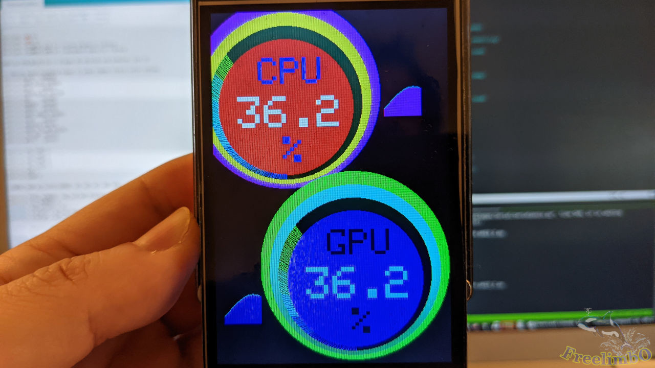
一切運作得如我所設計。太棒了!
就是這樣。😄 我接著將這個狀態面板安裝到電腦機殼的透明視窗上。在玩遊戲時,我可以透過這個小裝置輕鬆查看硬體狀態,同時不會佔用遊戲螢幕的任何顯示區域。